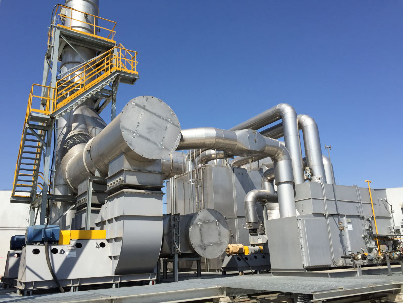
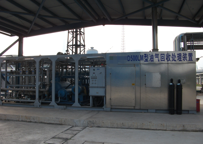
Oil & Gas Vapor Recovery Units (VRU)
PollutionCtrl provides project-specific vapor recovery systems for storage tanks, tank farms, loading racks, terminals, refineries and process vents. The recovery route is selected from vapor composition, flow pattern, pressure, temperature, oxygen content, liquid carryover risk, product value and the required recovery destination.
Choose the right vapor recovery process
| VRU category | Typical fit | Main process | Review first |
|---|---|---|---|
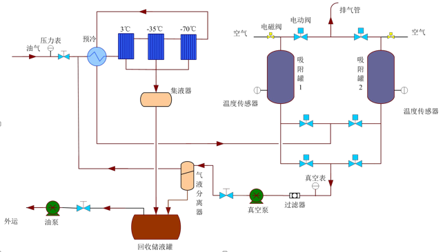
| Condensation + Adsorption VRU | Tank breathing, loading vapor and heavier hydrocarbon streams where recovered liquid has value | Staged cooling, condensate separation, adsorption polishing and desorption | Vapor composition, dew point, water, peak flow, refrigeration and liquid handling |
| Adsorption + Absorption VRU | Gasoline, light hydrocarbon and variable vapor streams requiring concentration equalization and deep treatment | Activated-carbon adsorption with absorption, solvent circulation and optional regeneration | Hydrocarbon compatibility, absorbent selection, oxygen/LEL, temperature and tail-gas target |
Typical vapor sources
- Fixed-roof and internal-floating-roof storage tanks
- Truck and rail loading racks
- Marine loading and unloading terminals
- Refinery and petrochemical tank farms
- Methanol, gasoline, diesel and solvent storage
- Process vents, blending, sampling and transfer operations
Safety and engineering scope
A complete VRU review includes source classification, vapor-header pressure balance, liquid knockout and drainage, flame-arrestor protection, grounding, hazardous-area electrical design, LEL and oxygen monitoring, nitrogen blanketing where required, emergency isolation, bypass and control logic.
Data required for preliminary selection
Provide the minimum, normal and peak vapor flow, gas composition, molecular weight, pressure, temperature, oxygen and moisture, liquid carryover, tank or loading data, simultaneous operating cases, recovery destination, emissions target and available utilities.
VRU manufacturer, engineering and supply scope
PollutionCtrl supplies packaged vapor recovery equipment for oil storage tanks, truck loading racks, terminals and process vents. The scope is built around the actual vapor source and site layout, rather than a fixed catalogue configuration.
Review vapor composition, peak flow, pressure, temperature, liquid carryover and recovery destination before equipment selection.
Supply skid-mounted recovery units with separators, compressors, condensers, adsorption beds, valves, instruments and controls.
Coordinate fabrication, piping, control-panel integration, inspection, packing, shipment and site handover.
Support installation, commissioning, spare-parts matching and operating reviews for overseas projects.
For a project discussion, start with the VRU equipment manufacturer and supply scope page, then review VRU sizing data, the RFQ data sheet and the installation and commissioning scope.
Request a preliminary VRU evaluation
Send the available gas data and operating conditions. PollutionCtrl can compare the two product routes and identify the measurements needed for preliminary sizing.
Related resources: refinery and tank terminal vapor control · VRU design for tank farms and truck loading · VRU troubleshooting.
Vapor Recovery Unit Design for Oil and Gas
PollutionCtrl supplies vapor recovery units for oil and gas storage, tank farms, terminals, truck loading and gasoline vapor control. A vapor recovery unit manufacturer should review tank pressure, vapor composition, flow variation, liquid carryover, compressor duty, recovery target, hazardous-area requirements and the operating pattern before final selection.
VRU system design may combine a compressor package, condensate or liquid separation, controls, piping, valves, instrumentation and recovery or discharge connections. The equipment arrangement should match the tank farm or terminal layout and the customer’s operating and maintenance requirements.
VRU Applications and Related Equipment
- Vapor recovery for refineries and tank terminals
- Truck loading vapor recovery system
- Marine vapor recovery system
- VRU compressor package
- VRU spare parts and service
- VRU design guide
VRU RFQ Information
For a VRU RFQ, provide tank volume, vapor source, peak and normal flow, pressure range, gas composition, temperature, liquid carryover risk, recovery destination, site classification and preferred control interface. This information helps determine the compressor, separator, piping and instrumentation package.
What is an oil and gas vapor recovery unit?
An oil and gas vapor recovery unit captures hydrocarbon vapor that would otherwise leave a storage or loading system. The equipment receives vapor from tanks, truck racks, terminals or marine loading points, separates entrained liquid, and then compresses, condenses, adsorbs or absorbs the vapor for recovery or controlled treatment.
Choose the process from the vapor data
There is no useful standard VRU size without site data. Two tanks with the same capacity can produce very different vapor loads because product volatility, filling rate, pressure control and ambient temperature are different. We start with the operating case, then select the process and equipment package.
| Design input | Why it matters | What to send |
|---|---|---|
| Normal and peak vapor flow | Sets the turndown range and peak equipment duty | Loading rate, filling cycle and simultaneous operations |
| Vapor composition | Affects condensation, compressor selection, materials and safety | Gas analysis with hydrocarbon range, moisture and contaminants |
| Suction and discharge pressure | Defines the compression duty and tank pressure constraints | Normal, minimum and maximum pressure at each connection |
| Liquid carryover | Can damage a compressor or reduce adsorption performance | Knockout arrangement, drainage method and upset history |
| Recovery destination | Changes the process arrangement and control philosophy | Return to storage, recovered liquid, fuel gas or downstream treatment |
| Site classification | Controls the electrical and instrumentation specification | Hazardous area, utilities, climate and local project requirements |
VRU applications are not interchangeable
- Tank farm and terminal vapor recovery must account for tank breathing, transfer schedules and pressure interaction between connected sources.
- Truck loading vapor recovery is usually governed by peak loading rate, loading arms, vapor headers and the number of bays operating together.
- Marine vapor recovery also requires review of the ship to shore interface, allowable vapor return pressure and emergency shutdown signals.
- Gasoline vapor recovery needs careful review of product composition, temperature, loading pattern and the route used to return or store recovered hydrocarbons.
What a VRU manufacturer should define before quotation
- Confirm the vapor sources and operating scenarios, including the credible peak case.
- Agree the battery limits for vapor inlet, liquid return, vent, drain, power, controls and utilities.
- Select the recovery process and VRU compressor package from actual pressure and composition data.
- Review alarms, trips, ESD, grounding, hazardous area equipment and access for maintenance.
- Issue the preliminary process description, equipment list, utility list and layout basis before final pricing.
What changes the cost of a vapor recovery unit?
VRU cost is driven by peak flow, pressure ratio, gas composition, recovery route, materials, hazardous area requirements, controls, utilities and the amount of site integration. A low initial price is not comparable if the separator, instruments, safety devices, commissioning or spare parts are outside the quoted scope. Use the VRU RFQ data sheet to request a scope that can be checked line by line.
Questions buyers often ask
Can one VRU serve several tanks?
It can, but the vapor header, pressure interaction, simultaneous transfer cases and isolation philosophy must be reviewed as one system.
Is a compressor always required?
No. The process depends on inlet pressure, recovery destination, vapor composition and the selected condensation, adsorption or absorption route.
What information is needed for a firm proposal?
Send the process description, vapor analysis, normal and peak flow, pressure range, temperature, operating schedule, site classification, utility conditions, layout and required delivery scope.
Vapor Recovery Unit Topics
- Vapor recovery compressor package
- Vapor recovery for oil storage tanks
- Tank farm vapor recovery system
- Oil terminal vapor recovery unit
- Marine loading VRU system
- Floating roof tank vapor recovery
- Tank breathing loss and VOC control
- Petroleum storage tank vapor recovery
- PC-VRU series overview
- VRU control panel and instrumentation
- VRU sizing and data checklist
- VRU purchase checklist
- Vapor recovery unit failure modes
- Liquid carryover troubleshooting
- High discharge pressure troubleshooting
- Petrol station vapour recovery
- Custom VRU systems
- VRU specification checklist
Vapor Recovery by Product Stream
- Ethanol vapor recovery system
- Methanol vapor recovery unit
- Benzene vapor recovery and control
- BTEX vapor recovery system
- Toluene vapor recovery unit
- Xylene vapor recovery system
- Naphtha vapor recovery system
- Condensate vapor recovery unit
- Crude oil vapor recovery system
- Mixed solvent vapor recovery
- VOC solvent vapor recovery equipment
- VOC condensation and adsorption system
- Adsorption and absorption for VOC recovery
- VRU for truck loading and tank farms
- Oil vapor recovery for tank farms, loading areas and gas stations
- VRU manufacturing facility
- Hydrocarbon vapor recovery equipment