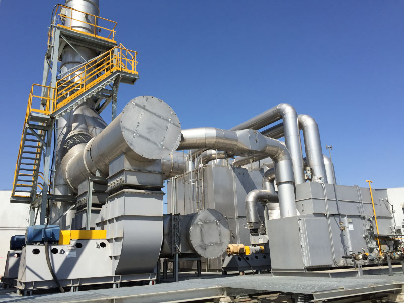

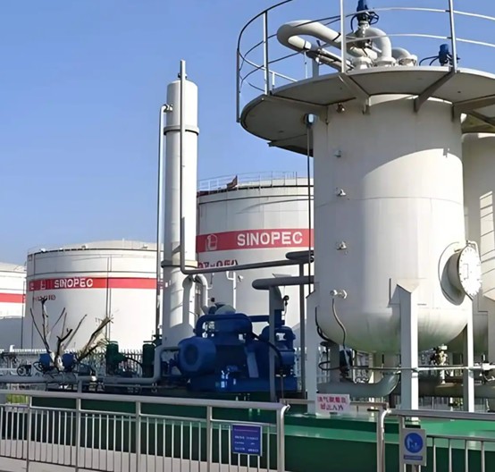
A vapor recovery unit captures hydrocarbon vapor from storage tanks, loading racks, terminals and process vents and returns it to a product stream instead of flaring or venting it. The design question is rarely which package to buy, but what the vapor stream does over a day, a week and a year.
This guide covers the inputs a design cannot be finished without, where each technology stops being the right answer, how the compressor relates to tank pressure control, and the scope boundaries worth settling early. See the oil and gas vapor recovery unit page for the equipment overview.
What a Vapor Recovery Unit Does
A VRU collects vapor from storage breathing, loading displacement, flash losses or process vents and recovers the hydrocarbons instead of destroying them. The recovered vapor may be condensed, adsorbed, absorbed, compressed or returned to a product system, depending on whether the recovered liquid has a home in the plant. Where recovery is uneconomic, oxidation is the more honest choice.
Common VRU Applications
- Oil and gas storage tank vapor recovery
- Gasoline loading and unloading vapor control
- Tank farm and terminal VOC recovery
- Petrochemical storage vapor treatment
- Marine vapor recovery during barge and ship loading
- Natural gas and hydrocarbon recovery on gathering sites
Terminals often combine several duties on one header: see refinery and tank terminal vapor control systems.
Design Inputs to Collect Before Selection
Most VRU projects that fail at commissioning were under-specified at inquiry, not badly built.
| Input | Why it changes the design |
|---|---|
| Vapor flow: normal, peak, minimum | Sets compressor size, line sizes and required turndown |
| Composition and molecular weight | Drives technology, compressor and materials selection |
| Stored medium and vapor pressure | Determines vapor generation and how far suction can be pulled |
| Loading frequency and simultaneous operations | Turns average flow into a credible peak case |
| Temperature, moisture, ambient and elevation | Affects condensation, freeze risk and cooling selection |
| Utilities available | Sets whether motors, air, water and steam are practical |
| Recovery target and emission limit | Fixes the performance the package must demonstrate |
| Safety, area classification and layout | Fixes instrumentation and whether the unit can be skidded |
Two inputs are consistently under-specified. The first is the peak: a VRU is sized for the worst credible coincident event, while a peak taken from a monthly average produces a unit that lifts tank relief valves. The second is vapor pressure at the highest expected storage temperature, which drives vapor generation. Our VRU RFQ data sheet and VRU sizing and data checklist are built around these fields.
Technology Selection: Where Each Option Fits
Adsorption and Absorption
Carbon adsorption suits moderate flows and concentrations where a high recovery fraction is required on a clean stream; beds regenerate under vacuum or a hot gas stream, and desorbed vapor is condensed and returned to liquid. Carbon dislikes heavy ends, water and polymer-forming contamination. Absorption is simpler where an absorbent already exists on site, but weaker on light ends.
Condensation
Condensation fits rich streams, low flows and cases where the recovered liquid is saleable. It is staged — a first cooler, then a refrigerated stage — with water and heavies freezing as the practical limit. Alone, it rarely meets a stringent final limit at low concentration.
Compression Plus Absorption
The workhorse at tank farms, terminals and loading racks: the compressor pulls vapor from tanks or loading headers, cools and separates it, then absorbs it or returns it to a product line. It handles high peaks because it can be staged, and recovers liquid in a usable form, but it is sensitive to carryover and fouling.
Membrane Separation
Membranes suit hydrocarbon-rich streams with a valuable permeate and retrofits where footprint is tight. Performance falls off with water and heavy contamination, so pretreatment is not optional.
When Recovery Is Not the Right Answer
Below a certain concentration, recovery becomes an expensive way to move a small amount of hydrocarbon around; there, oxidation is simpler to prove. The deciding inputs are concentration, continuity, and whether the recovered liquid has a destination. That logic is set out under VRU engineering and system design.
Compressor Package and Tank Pressure Control
Suction Pressure Band and Deadband
The unit holds the suction header inside a pressure band set from tank design pressure and vent settings with margin. Too low a set point wastes power and drags liquid to the suction; too high and tank breathing valves lift before the compressor corrects. The deadband must prevent short-cycling.
Buffer Volume and Header Interaction
The suction header is a buffer: more volume between sources and compressor smooths a sudden displacement before the machine sees it. Where tanks and package are far apart, header size becomes part of the control scheme; restricted lines turn a manageable peak into a pressure excursion.
Capacity Control and Staging
Capacity must cover near-zero on a cold night through the design peak. Options are variable-speed drive, cylinder unloading, recycle with a cooler, or a second machine; recycle should be the last resort, since it costs power and heats the suction gas. Package detail sits under the VRU compressor and vapor recovery compressor package pages.
Piping, Knockout and Carryover Prevention
Liquid in a vapor line causes more difficult startups than anything else, so the piping has one priority: keep liquid out of the compressor suction.
- Slope vapor headers toward the sources or a collection point; no flat runs, and a drain at every low point.
- Size the inlet knockout drum for the design peak plus a credible slug, with level indication the control system acts on.
- Fit a mist eliminator downstream, keeping vapor inside its design velocity range.
- Keep the suction line short and generously sized to limit pressure drop.
- Return recovered liquid to a confirmed destination, not a drain.
Routing and the maintenance access it implies are covered under piping and maintenance considerations for vapor recovery units.
Control, Instrumentation and Records
A VRU is a small process plant: a PLC-based controller with a defined start-stop sequence and an explicit interlock list.
- Pressure transmitters on suction, discharge and the controlled header, ranged for the actual band.
- Level transmitters on the knockout drum, with high-level shutdown separate from the high-level alarm.
- Temperature monitoring on compression and any refrigerated stage.
- Interlocks to stop or unload on high level, high discharge pressure or temperature, low suction, and loss of the liquid destination.
- Data logging of the parameters tied to the emission limit, with alarm history for troubleshooting.
Operated outside its design envelope, the mechanisms recur; they are described under VRU failure modes.
Packaging, Site Verification and Delivery Boundaries
Scope causes more disputes than technical faults, so agree what is skidded, what is field-erected and who supplies each tie-in.
- Skid versus stick-built. A skid cuts field work and commissioning time but is limited by transport size, weight and lifting.
- Site verification. Confirm tie-in elevations, power and air availability, transport access and the condition of existing tanks.
- Installation and commissioning. Define who sets, connects and starts the package, and what test proves performance.
- Spares. Base a holding on compressor, instrumentation and media lead times.
Frequently Asked Questions
How do I size a vapor recovery unit?
Start from vapor generation, not tank volume: the normal vapor rate plus a credible peak from coincident loading and filling, at the highest expected storage temperature.
Which technology suits a tank farm or loading rack?
Compression with absorption or adsorption is the practical default, handling high peaks and recovering usable liquid. Condensation fits rich low-flow streams, membranes tight footprints, carbon clean moderate streams.
What suction pressure should the VRU control to?
Low enough to stay clear of tank vent settings under normal breathing, high enough that the machine is not pulling harder than generation justifies. It is set per site from tank design pressure.
What happens if liquid reaches the compressor?
The outcome ranges from lost capacity and unstable control to mechanical damage. That is why a knockout drum, a mist eliminator and an independent high-level shutdown sit ahead of the compressor.
Can a VRU be retrofitted to an existing tank battery?
Usually yes, and retrofit is often the better commercial case. Constraints are the tank pressure ratings, space for the package and header, and whether existing vapor piping can be reused.
Talk to an Engineer
Send your vapor flow range, composition, stored product and site constraints, and we will return a technology recommendation and a proposed scope boundary. Use the contact page to reach an engineer directly.