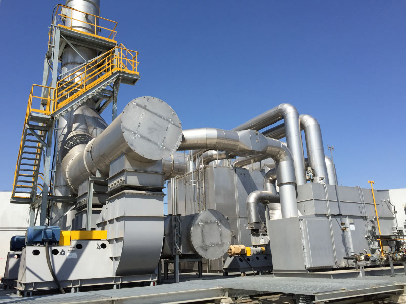

This case covers a standard three-chamber regenerative thermal oxidizer for comprehensive VOC treatment at a large chemical park, where tank farm exhaust, process waste gas and intermittent loading emissions are collected into one train – a mixed, chemically awkward stream under a permit requirement that extends beyond VOC to dioxin control.
Case Background and Emission Profile
The system is applied to a large chemical park for centralized treatment of tank farm exhaust, production process waste gas and loading/unloading intermittent exhaust. The waste gas contains vinyl acetate, ethylene, methanol, aldehydes and esters, with mixed continuous and intermittent working conditions. Strict requirements are put on pollutant removal, dioxin control and overall compliance.
| Emission characteristic | Design consequence |
|---|---|
| Oxygenated species, including an unsaturated compound | Readily oxidizable, but can foul a catalyst surface |
| Multiple sources: tank breathing, vents, loading | Collection, not point-source control; each stream needs its own case |
| Continuous and intermittent duty with peak events | Turndown and stability matter as much as peak capacity |
| Sulfur and chlorine species, seen as SO₂ and HCl | Acid-resistant materials; catalyst route ruled out |
Why Thermal Oxidation Rather Than Catalytic, Adsorption or Concentration
A catalytic oxidizer would cut operating temperature and fuel demand, but catalyst systems fail where halogen or sulfur species are present or where compounds can polymerize and mask the surface, making catalyst life a commercial risk on this stream.
A thermal oxidizer removes that risk at higher fuel demand, and regenerative heat recovery closes the gap: cleaned gas preheats incoming exhaust through ceramic media, so the burner supplies only the difference. A dedicated purge chamber holds recovery high while the flow path reverses.
Adsorption is not a treatment route at this scale – spent carbon remains a waste stream – so it sits at the end of the train as a polishing layer, which is how it is used here. Rotor concentration suits dilute, high-volume streams but adds complexity this one does not justify, and rotary valve RTOs win where space is tight; here the three-chamber arrangement and a modular layout were kept.
Key Design Inputs and Selection Steps
Sizing starts from eight data items: design flow at peak and normal cases; VOC species and concentration; the permit limit that fixes required destruction efficiency; halogen, silicon, phosphorus and heavy-metal content, deciding catalyst viability; particulate loading and moisture; turndown and operating pattern; site conditions, elevation, and available fuel and power.
The sequence then follows a fixed order:
- Build the heat balance first – VOC heat release against the heat needed to reach oxidation temperature – to establish whether the unit is autothermal or needs support fuel
- Set the oxidation condition from the hardest requirement on the stream, here dioxin control rather than the VOC limit
- Size ceramic media volume for target recovery and allowable pressure drop, checked against stream fouling
- Choose chamber configuration for purge quality and turndown, then materials for corrosive species formed after oxidation
- Finally fix the exhaust train: quench, deacidification, carbon injection and filtration, per our RTO sizing guide
Scope of Supply and Key Components
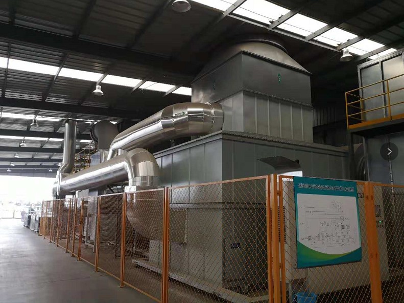
The supplied scope was a full-process train: Buffer Separator + Baghouse + RTO + Secondary Combustion Chamber + Quenching Tower + Deacidification + Activated Carbon Adsorption. The path runs Mixed Waste Gas → Buffer Gas-Liquid Separator → Baghouse → RTO & Secondary Combustion Chamber → Flue Gas Quenching Tower → Semi-dry Deacidification → Activated Carbon Injection → Baghouse → High-Altitude Discharge.
| Stage | Components | Role |
|---|---|---|
| Inlet conditioning | Buffer separator, baghouse | Removes carryover and particulate ahead of the ceramic media |
| Oxidation | Three-chamber RTO, secondary combustion chamber, burner (1 operating + 1 standby) | Above 850℃ for over 2 seconds to decompose VOC and dioxin precursors |
| Quench | Flue gas quenching tower | Below 200℃ within 1 second, avoiding the 200-400℃ dioxin range |
| Acid and residual removal | Semi-dry deacidification, carbon injection, baghouse | Removes SO₂ and HCl, then adsorbs residual VOC and heavy metals |
| Solids and control | Sealed conveying, slag removal, PLC interlocks | Conveys residue out; supervises fan, flame, pressure, temperature |
Two groups decide long-run availability: the switching valves, which must seat reliably through continuous cycling, and the safety interlock system.
Commissioning and Verification
Commissioning should be scheduled, not improvised:
- Cold checks and burner tuning – ducting and valve seating, instrument loops, fan rotation, control sequence dry run, then holding temperature on the measured stream against the design heat balance
- Controlled heat-up – gradual, so expansion and refractory dry-out are progressive, reading the bed temperature profile and not only the chamber setpoint
- Purge and switching verification – the purge must clear the bed before flow reverses, checked on pressure and flow signals
- Interlock testing – bed and chamber high temperature, fan failure, flame loss, pressure deviation, quench or utility loss, tripped in turn
- Downstream stabilisation, then performance testing – dosing, quench control and carbon injection set before the emission test, which measures destruction efficiency by the permit method
Recorded performance: VOC destruction efficiency ≥ 98%, dioxin ≤ 0.1 ng TEQ/m³, and particulate matter and acidic gas meeting national standards. Single or multiple waste gas stream operation allows maintenance on one source without stopping the train, and a 95% heat recovery rate lets the system run without auxiliary fuel at medium and high VOC concentration.
Operation, Maintenance and Common Pitfalls
Three habits carry reliability: a clean inlet, switching hardware and purge sequence kept in specification, and trends read over thresholds. Carryover shows up as media pressure drop long before it shows up as an exceedance – see our RTO inspection guide.
- Trend media pressure drop per bed; a skewed bed points to distribution, media or valve problems
- Inspect switching valve seats and actuators on a fixed cycle, and re-check purge timing after any adjustment
- Verify instruments on schedule, check quench nozzles and water quality, and keep dosing calibrated
Common Pitfalls
- Sizing to averaged flow and discovering the peaks are the real design case
- Treating dioxin control as a downstream add-on instead of one temperature-and-quench system
- A catalyst route on a halogen-bearing stream without a species review, or routine interlock bypasses
What Transfers to Similar Projects
A multi-source chemical park stream is a collection problem before it is an oxidation problem: buffering, liquid separation and peak-case design make the oxidizer predictable. Where a permit adds a dioxin requirement, the temperature and quench path becomes the governing design case from the start. Adsorption belongs at the end as a safeguard, never as primary control. Modular layout is what makes such a train viable for old plant renovation as well as new build.
Frequently Asked Questions
Why a three-chamber RTO rather than a two-bed design?
A two-bed unit reverses flow between two beds and must purge so untreated gas does not reach the stack at each switch. A dedicated purge chamber handles that volume without compromising treatment path or recovery rate.
Why add a secondary combustion chamber?
The RTO stage performs the bulk of VOC destruction at high recovery. The secondary chamber adds a controlled high-temperature stage with residence time, specified here for the species and precursors targeted by dioxin control.
How is destruction efficiency demonstrated?
By testing the operating unit on a representative stream at stable conditions, using the method the permit specifies. Results hold only over the range tested, so that envelope is documented and the unit run inside it.
Which interlocks matter most?
Fan operation, flame presence, chamber and bed temperature and system pressure are the core set, with quench and auxiliary failure included. On a high-temperature excursion, fan loss or quench failure, stop the gas path safely.
How much of this design is reusable elsewhere?
The method, not the numbers. The same data set, heat-balance-first approach, configuration and materials sequence apply to any mixed VOC stream, while size, media volume and downstream scope must be re-derived.
Talk to an Engineer
Send your stream data – flow, species, concentration, halogen and particulate content, permit limit and site constraints – and we will assess whether a three-chamber RTO train fits your case or recommend a different configuration. Reach us at pollutionctrl.com/contact.