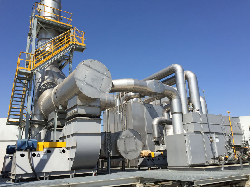

RTO Switching Valves and Flow Distribution
Switching valves direct untreated and treated gas through the ceramic beds. Leakage, actuation speed, sealing condition and switching logic directly affect carryover, pressure stability, destruction efficiency and maintenance.
Discuss your RTO projectWhat should be evaluated during component selection?
Valve arrangement
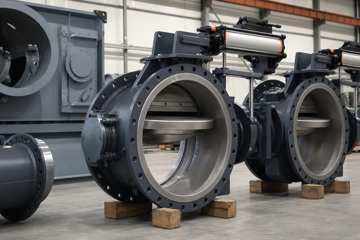
Two-bed and three-bed RTOs commonly use poppet, damper or other switching arrangements. Rotary systems use a distribution valve and segmented bed. The arrangement must match airflow and required performance.
Sealing and carryover
Internal leakage can allow untreated gas to bypass the combustion path. Seal design, seating force, purge strategy and inspection access are therefore central to performance.
Switching dynamics
Opening and closing sequence affects duct pressure and process-room balance. Actuator sizing, cycle time and PLC logic are coordinated to reduce production disturbance.
Actuation and utilities
Pneumatic or electric actuation is selected according to speed, fail position, available utilities, hazardous-area requirements and maintenance preference.
Temperature and material selection
Valve bodies, shafts, seals and bearings are selected for gas temperature, chemical exposure and switching frequency. Expansion and alignment must be considered.
Inspection and service
Cycle counts, stroke time, leakage indicators and actuator condition should be trended. Accessible seals and wear parts reduce shutdown duration.
Component performance must be evaluated at system level
An RTO is not a collection of independent parts. Media pressure drop changes fan duty; valve leakage affects destruction efficiency; burner turndown affects temperature stability; and PLC logic coordinates each operating state.
Final selection should be based on the complete waste-gas analysis, required outlet limits, operating schedule, site utilities and maintenance strategy.
Related RTO technical pages
RTO Switching Valves and Flow Distribution questions
How do switching valves affect VOC destruction efficiency?
Leakage and residual gas trapped during switching can create carryover. Valve sealing, purge logic and system configuration are selected to control this effect.
What are signs of valve problems?
Unstable pressure, abnormal stroke time, increased actuator demand, unusual noise, temperature imbalance and declining removal efficiency may indicate inspection is required.
Are rotary valves maintenance-free?
No flow-distribution mechanism is maintenance-free. Seals, bearings, drive components, alignment and leakage should be included in the preventive-maintenance plan.
Send your VOC data for preliminary RTO sizing
Share airflow, VOC composition, concentration range, inlet temperature and operating schedule. Our engineering team will review the process conditions before recommending a configuration.
RTO switching valve and maintenance points
Switching valves determine how the RTO sends exhaust gas through the heat-recovery chambers. Valve selection should consider temperature, pressure difference, switching frequency, sealing performance, actuator response and access for maintenance.
- Valve size, pressure drop and actual peak airflow
- High-temperature materials, seat sealing and thermal expansion
- Pneumatic or electric actuator, position feedback and response time
- PLC sequence, valve-position confirmation and fault interlock
- Inspection of seals, actuator, limit switch and leakage during service
For replacement or troubleshooting, send valve nameplate, actuator details, alarm record and a photo of the installation. See the switching valve maintenance guide and the RTO safety interlock page.