
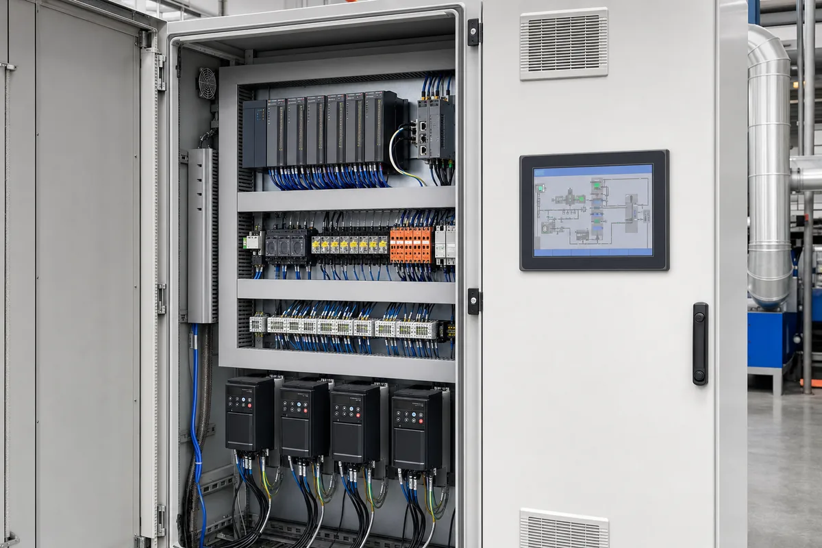
RTO PLC Control System and Safety Interlocks
The RTO control system coordinates purge, start-up, burner management, fan control, valve switching, temperature protection, process permissives and shutdown. The operating philosophy should be defined with the production process and site safety requirements.
Discuss your RTO projectWhat should be evaluated during component selection?
Start-up and purge sequence
Automated permissives confirm airflow, valve position, instrument status and purge completion before ignition and process introduction.
Temperature and pressure control
Multiple temperature points, differential pressure, duct pressure and fan VFD control help maintain the oxidation chamber and protect the process connection.
LEL and concentration management
Where required, LEL or VOC monitoring supports alarms, dilution, load management and emergency actions. Sensor location and response time are application-specific.
Burner management and flame safety
Ignition, flame proving, fuel shutoff, pressure switches and trip logic are integrated with the RTO sequence and applicable burner-safety requirements.
Data logging and remote support
HMI trends, alarm history, cycle counters, fuel use and operating temperatures support compliance records, troubleshooting and preventive maintenance.
Process interlocks
Production fans, dampers, ovens, coating lines or other sources are coordinated so abnormal RTO conditions trigger the correct safe response without creating a secondary hazard.
Component performance must be evaluated at system level
An RTO is not a collection of independent parts. Media pressure drop changes fan duty; valve leakage affects destruction efficiency; burner turndown affects temperature stability; and PLC logic coordinates each operating state.
Final selection should be based on the complete waste-gas analysis, required outlet limits, operating schedule, site utilities and maintenance strategy.
Related RTO technical pages
RTO PLC Control System and Safety Interlocks questions
Which parameters should an RTO HMI display?
Typical values include chamber and bed temperatures, inlet and outlet pressure, media differential pressure, valve position, fan speed, burner status, alarms and operating mode.
Can an RTO be monitored remotely?
Remote monitoring can be provided when permitted by the customer cybersecurity policy. Access control, logging and separation from safety functions should be defined during engineering.
What happens during an RTO trip?
The safe sequence depends on the hazard review and connected process. Fuel is isolated and process gas is diverted, stopped or diluted according to the approved cause-and-effect logic.
Send your VOC data for preliminary RTO sizing
Share airflow, VOC composition, concentration range, inlet temperature and operating schedule. Our engineering team will review the process conditions before recommending a configuration.
RTO control system and safety logic
An RTO control system must coordinate burner startup, purge, valve switching, chamber temperature, fan operation, pressure, alarms and emergency shutdown. The control sequence should be reviewed against the actual equipment and site operating procedure.
- Valve position feedback and switching sequence confirmation
- Burner management, flame failure, purge and fuel shutoff
- High-temperature, low-temperature, high-pressure and fan-failure alarms
- LEL, oxygen, VOC or process interlocks where required
- Manual, automatic, bypass and emergency shutdown modes
Provide the I/O list, alarm list, process sequence and hazardous-area requirements during design. The control scope should be linked to the switching valves, burner system and main RTO system.