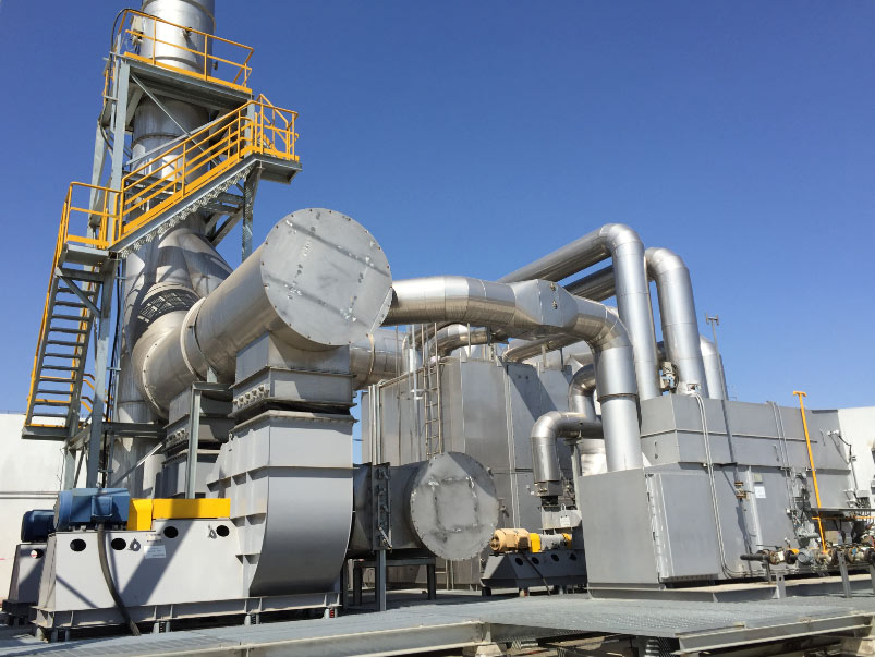

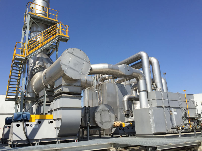
A zeolite concentration rotor combined with a three-chamber regenerative thermal oxidizer was installed on the coating lines of an automobile parts plant. The exhaust is a classic painting-shop profile – high volume, low to medium VOC concentration, paint mist from the booths – so the process concentrates first and incinerates second.
Project Background and Exhaust Characteristics
The project targets the coating production lines of Lizhong Light Alloy (Anhui). There are 2 painting lines including primer, topcoat, flow-out and drying processes. The waste gas mainly comes from volatile paint and diluents, containing xylene, non-methane total hydrocarbons and paint mist. It is typical large air volume, low-medium concentration VOC waste gas. A single RTO would lead to high operating costs, while paint mist is easy to block conventional treatment equipment.
Core Parameters and Process Configuration
| Parameter | Value |
|---|---|
| Total gas treatment capacity | 154,000 Nm³ |
| Max gas temperature | ≤ 40°C |
| Emission standards | DB34/4812.6-2024, GB16297-1996 |
- Combined process – Multi-stage Dry Filter + Zeolite Concentration Rotor + Three-Chamber RTO (concentration first, then incineration to cut operating costs)
- Process flow – Painting Waste Gas → Multi-stage Dry Filter → Zeolite Rotor → Desorbed High-Concentration Waste Gas → RTO → Plate Heat Exchanger → Standard Discharge
- Pretreatment – four-stage graded filters (G4/G7/F9) intercept paint mist and particles to avoid blockage of the zeolite rotor
- Concentration unit – hydrophobic zeolite rotor at 1.1∼1.4 rph, concentration ratio about 15, desorption controlled at 180∼220°C
- Incineration unit – VOC completely oxidized at 800∼850°C inside the RTO, heat recovery efficiency up to 95%
- Waste heat reuse – flue gas heat is recycled by the plate heat exchanger to supply rotor desorption
- Main equipment – multi-stage bag filter, differential pressure alarm device, large hydrophobic zeolite rotor, three-chamber RTO, low-NOx burner, frequency conversion fans, online VOC monitor, digital twin monitoring system
Why Zeolite Concentration Plus RTO Instead of Direct Combustion
Thermal oxidation running cost is governed by how much gas must be heated, not how much VOC must be destroyed. Supplemental heat scales with mass flow through the chamber, the temperature rise and the media’s heat recovery effectiveness, and at thin concentrations the VOC covers only a small part of it. Dilute gas in large volume therefore means a permanent fuel bill.
Concentration moves the duty back into the economic range. The rotor adsorbs solvent onto hydrophobic zeolite while the cleaned bulk of the air passes to atmosphere, then releases that solvent into a much smaller desorption airflow. A small volume now carries the whole VOC load, so the oxidizer sees a fraction of the original flow at a multiple of the original concentration, and the VOC heat value covers a far larger share of the heat balance. High-volume, low-concentration exhaust from painting lines and printing operations is handled the same way, usually as a rotary concentrator package; on clean, high-concentration streams a direct thermal design stays correct.
Key Design Inputs and How the Selection Was Made
- Flow basis – every extraction point and oven exhaust, with normal, maximum and minimum cases agreed at the oxidizer inlet, including temperature, humidity and dilution air.
- VOC characterisation – species or dominant solvents, a concentration range rather than one value, and a check for halogen, silicone, phosphorus and heavy metals.
- Particulate – paint mist and overspray loading, droplet size and tackiness, which set the filtration stages and their change-out interval.
- Operating pattern – continuous, shift-based or campaign production and how lines start and stop, which sets turndown and standby logic.
- Heat balance – VOC heat value at inlet concentration against the heat needed to reach oxidation temperature through the recovery media; this decides whether concentration is justified, and how much recovered heat can return to desorption.
- Concentrator sizing – face velocity, media volume and rotor speed from the flow and required cycle, with desorption airflow set to deliver the target concentration ratio.
- Oxidizer sizing – chamber volume, residence time, media volume and pressure drop from the desorbed flow and destruction target; see the RTO sizing guide and RTO ceramic media.
Coupling Between the Rotor and the RTO
Desorption Ratio and Concentration Ratio
Desorption airflow sets everything downstream: more of it gives the oxidizer more gas to heat at lower concentration, while less gives a smaller, cheaper oxidizer but risks incomplete desorption and solvent carry-over to the clean side. The concentration ratio is total gas volume divided by desorption volume, so rotor speed, media volume, desorption airflow and temperature are chosen together to hold it – here 1.1∼1.4 rph at about 15, desorption at 180∼220°C.
Heat, Bypass and Interlocks
- Heat integration – desorption air must reach its set point, and the cheapest source is heat the oxidizer has already recovered, which the plate heat exchanger supplies here.
- Bypass paths – a rotor-offline bypass keeps lines running during rotor maintenance where the permit allows it; a cool-down or high-temperature bypass protects media and rotor during upsets.
- Interlocks – airflow proving, rotor rotation, desorption and chamber temperature and filter differential pressure must be proven before solvent reaches the rotor or oxidizer, and a deviation drives a defined sequence, not an operator decision (RTO control system and safety interlocks).
Testing, Commissioning and Acceptance
- Works testing – mechanical and electrical checks, rotor rotation and speed control, burner and gas train function, valve sequencing, and a loop check of control logic and interlocks.
- Site commissioning – airflow balancing, rotor run-in, gradual heat-up and media conditioning, burner light-off and turndown, tuning of concentration and desorption set points, and verification that interlocks trip and reset.
- Acceptance – test conditions, sampling locations and the parameters to be proved are agreed in advance, then destruction performance, stack concentration, chamber temperature and pressure drop are confirmed together (RTO inspection guide).
Verified performance here: non-methane total hydrocarbon ≤ 60 mg/m³, xylene ≤ 20 mg/m³, particulate matter ≤ 120 mg/m³. The rotor reduces the treatment air volume of the RTO, cutting natural gas consumption by more than 40%.
Operation and Maintenance
- Filtration first – filter differential pressure is the most useful indicator on the plant: changed on time it protects the rotor, ignored it lets paint mist reach the media.
- Rotor and media – monitor rotor pressure drop and the desorption-side temperature profile; rising pressure drop at stable flow means fouling or incomplete desorption, and clean-side concentration against desorption set points shows whether the zeolite still performs.
- Valves and controls – seating, timing and seal condition drive emission consistency and pressure-drop stability (RTO switching valves).
- Heat recovery and burner – clean media and correct burner tuning hold recovery efficiency; drifting outlet temperature at steady inlet is the first sign of wear.
- Monitoring – the digital twin monitoring system provides real-time status monitoring, fault early warning and remote management, supporting unattended operation.
Frequently Asked Questions
Why not install a larger RTO and burn the whole stream?
Because running cost scales with gas volume, not VOC. Most of the fuel would heat air carrying very little solvent, and the oxidizer would grow in proportion. Concentrating cuts both the flow heated and the package size.
Does concentration change the destruction efficiency?
No. At the design chamber temperature, with adequate residence time and mixing, VOC is destroyed the same way whatever the inlet concentration.
How is paint mist handled?
By staged filtration ahead of the rotor: four graded filter stages (G4/G7/F9) intercept paint mist and particles, with differential pressure alarms to flag change-out.
Can the plant run when production is intermittent?
Yes. Turndown, standby temperature and bypass logic follow the real production pattern, so the rotor and oxidizer hold a ready state instead of repeatedly cold starting.
What should be agreed before the equipment is ordered?
Flow cases, VOC species and concentration range, particulate loading, operating schedule, applicable emission limits, and the performance figures to be proved with their test conditions.
Talk to an Engineer
Send your stream data – flow cases, solvent species, concentration range, particulate and moisture, operating schedule and the limits you must meet – and we will say whether concentration is justified or a direct thermal design is the better answer (contact us).