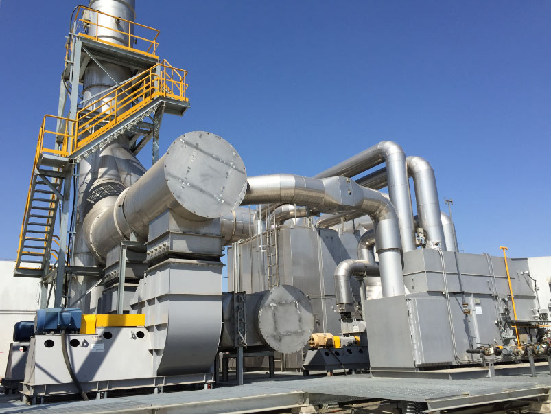

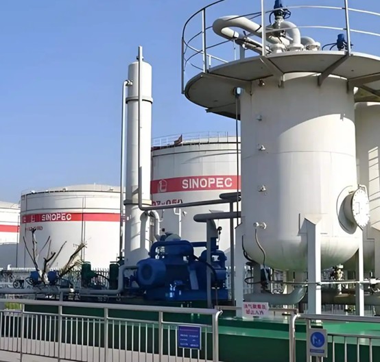
A storage tank vapor recovery system collects vapors displaced during tank filling, breathing and product flashing. The project may look like a simple pipe-and-fan installation, but reliable recovery depends on vapor-rate estimation, pressure control, liquid management, safe piping and the correct recovery technology.
This design guide covers the main decisions for oil terminals, tank farms, chemical storage and upstream oil and gas facilities.
Define the vapor sources
Start by listing every connected tank and operating event. Filling losses occur when incoming liquid displaces vapor. Breathing losses follow temperature and atmospheric pressure changes. Flash gas can be released when a pressurized liquid enters a lower-pressure tank. Loading racks, separators and process vents may add intermittent peaks.
Normal flow, maximum simultaneous flow and short-duration peak flow should be estimated separately. A system sized only from average throughput may experience high tank pressure or frequent bypass during peak events.
Collect vapor without upsetting tank pressure
The vapor header should minimize pressure drop while preventing air ingress and liquid accumulation. Each tank requires appropriate isolation, pressure control and independent pressure-vacuum relief protection. The recovery unit is an operating control device; tank relief valves remain safeguards.
Headers should slope toward safe drain or knockout points. Low spots can collect hydrocarbon liquid, restrict vapor flow and send slugs into downstream equipment. See our guide to VRU piping and maintenance.
Install effective liquid separation
A knockout vessel protects compressors, blowers and carbon beds from liquid carryover. Vessel volume, inlet device, mist separation, level indication and high-level shutdown should match the expected liquid mechanism. Automatic drains must discharge to a safe closed destination.
Select the recovery method
Compression VRU
Compression is suitable when recovered gas can enter a fuel-gas, gathering or sales system at a defined pressure. Capacity control must handle turndown without excessive cycling.
Carbon adsorption vapor recovery
Activated carbon systems can capture hydrocarbons from loading and storage vapor. Regeneration and vacuum equipment are selected around vapor composition, humidity and operating cycle.
Condensation or absorption
Cooling and compression can condense heavier hydrocarbons. Absorption transfers selected vapor components into a compatible liquid. These methods may be combined with other stages.
Explore our oil and gas vapor recovery unit and VRU selection article.
Instrumentation and control
- Tank or header pressure transmitters for capacity control.
- Flow measurement where performance tracking is required.
- Knockout vessel level indication and high-high shutdown.
- Suction and discharge pressure monitoring.
- Gas and bearing temperature monitoring where applicable.
- Emergency shutdown, grounding and hazardous-area electrical design.
Control setpoints should keep the header within the safe operating pressure of all connected tanks. A lead-lag arrangement may be useful when vapor flow changes widely or uninterrupted recovery is required.
Manage air ingress
Leaking hatches, open drains and poorly controlled vents can pull air into the vapor system. This reduces hydrocarbon concentration, increases equipment load and can create an undesirable flammable mixture. Leak inspection and oxygen monitoring may be needed depending on the process and recovery technology.
Plan for upset and maintenance
Define what happens during power loss, high tank pressure, high liquid level, compressor shutdown and maintenance. A safe backup path may route vapor to another control device. Isolation should allow equipment service without leaving tanks unprotected.
Data checklist for a design proposal
- Tank count, dimensions, product and throughput.
- Liquid inlet pressure and temperature.
- Vapor composition, including water and corrosive components.
- Minimum, normal, maximum and peak vapor rates.
- Allowable tank pressure and existing relief settings.
- Recovered-gas destination pressure.
- Ambient conditions, utilities and area classification.
Recovery or combustion?
Recovery is attractive when the hydrocarbon stream has reusable value and a stable destination. For low-value, contaminated or highly variable vapor, an oxidizer or enclosed combustor may be more practical. Lifecycle evaluation should include product recovery, electricity or fuel, maintenance, emissions and backup requirements.
Contact PollutionCtrl to review tank vapor recovery system design, equipment selection and integration.
Vapor Recovery Technical Resource Center
Need a direct VRU recommendation? PollutionCtrl can compare compression, condensation, adsorption, absorption and vapor combustion from vapor composition, flow, pressure and recovery destination.