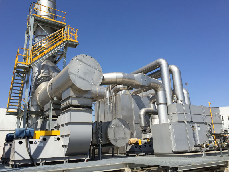

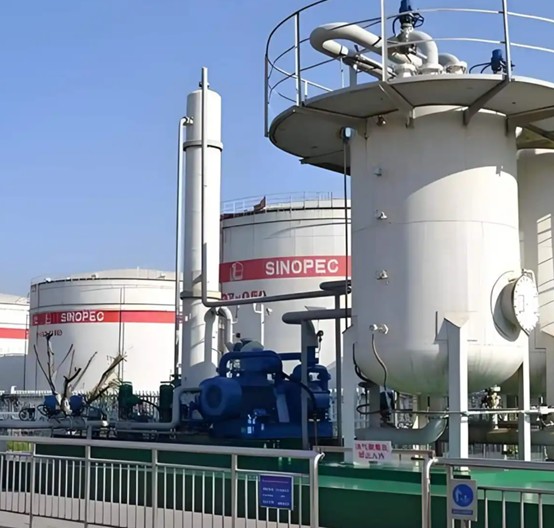
Direct answer: Refinery and tank terminal vapor control combines closed vapor collection with either recovery or oxidation. Use a vapor recovery unit when the hydrocarbon can be returned to the process as gas or liquid; use a vapor combustion unit or an oxidizer when the vapor has little recovery value, fouls adsorbents or poisons catalyst, or has no safe destination.
Where Refinery and Terminal Vapors Come From
Most projects fail at collection, not at the skid. Each source carries its own pressure limit, flow pattern and contamination risk, and one shared header invites backpressure, air ingress or carryover.
Storage tank breathing and filling losses
The largest continuous source at most terminals, driven by temperature swing, filling displacement and product vapor pressure. Control is normally a closed line to a VRU for floating roof tanks, with allowable tank pressure as the binding constraint.
Loading: truck, rail, ship and barge
The highest instantaneous flows on site, produced in batches. Vapor balance, adsorption, absorption and condensation are the usual recovery routes, with combustion as the fallback.
Blending, sampling and transfer
Inline and in-tank blending, sampler purges and inter-tank transfers release small volumes with wide composition swings. Sealing or return to tank is usually enough.
Wastewater and oily water systems
Sump headspaces, separators and slop systems release hydrocarbon stripped from water – low flow, continuous, wet and often odorous. Balanced collection routes it to recovery when the hydrocarbon has value, or to oxidation when it is dilute.
Fugitive leaks and process vents
Leak detection and repair plus better sealing handle the diffuse component. Once captured, that vapor must be sized and pressure-protected. Blowdown and batch process vents normally go to a flare, combustor or oxidizer.
Matching the Control Scheme to the Source
| Source character | Usual control route |
|---|---|
| Clean, dry tank breathing vapor | Recovery – adsorption, absorption or condensation |
| Loading vapor with a return path to the vessel | Vapor balance, with recovery for the surplus |
| Wet, odorous vapor with little value | End-of-pipe oxidation |
| Dilute, large-volume header exhaust | Regenerative thermal oxidizer |
| Rich vapor with no recovery destination | Direct-fired thermal oxidizer |
| Sources with conflicting pressure limits | Segregated headers, independent relief |
The full screening logic is in our tank farm and truck loading vapor recovery design guide.
Recovery First: How a VRU Is Built
- Adsorption – beds capture hydrocarbon, then regenerate under vacuum or a sweep gas. Suited to lighter, clean vapors; heavy ends and water shorten bed life, and the tail gas still carries hydrocarbon.
- Absorption – a vapor recovery tower contacts vapor with a circulating liquid. Performance depends on equilibrium, temperature, pressure and mass transfer, and the absorbed hydrocarbon needs a destination.
- Compression and condensation – a vapor recovery compressor raises pressure and refrigeration condenses the heavier fraction, which suits rich streams where liquid product returns to storage.
- Vapor balance – displaced vapor returns to the delivering or receiving vessel. Inexpensive where products match and the vessel accepts the return.
Surge volume, liquid knockout, pressure control and interlocks are where most system problems are solved; that scope sits under VRU engineering and system design.
When Recovery Alone Is Not Enough
Recovery and oxidation are stages of one strategy. Two conditions push a project to add end-of-pipe oxidation:
- Gas that cannot be fully recovered. Beds, absorbers and condensers are never perfect closed loops: regeneration produces a hydrocarbon-bearing tail gas, and a condenser removes only what condenses at the chosen pressure and temperature.
- Gas that should not be recovered. Dilute or highly variable header vapor, wet streams, and vapor carrying compounds that foul adsorbents or poison catalyst.
A VRU alone is normally sufficient for clean, dry, single-product vapor with a genuine return destination and predictable flow. Where both stages are used, size recovery first and take the oxidizer duty from the measured tail gas. Typical destruction-stage choices are a regenerative thermal oxidizer for dilute, high-volume exhaust and a thermal oxidizer for rich or contaminated streams.
Loading Terminals: Truck, Rail and Marine
- Batched, high flow. Long idle periods are broken by short peaks that follow the loading rate. Simultaneity of bays, not the sum of every bay, sets the design basis.
- Product switching. One rack may load gasoline, naphtha, distillate and ethanol, and cross-contamination affects performance and product quality.
- Hazardous area classification. Loading areas and vapor piping are classified zones, so skid boundary, vent location and instruments follow that rating.
- Spill prevention and bonding. Loading arms, dry-break couplings, overfill protection and vehicle high-level alarms stop a vapor system becoming a liquid release path. Bonding and grounding is essential – an unearthed vehicle plus hydrocarbon vapor is a known ignition scenario.
- Vessel pressure limits. Returned vapor cannot exceed the tanker or barge allowable pressure, and that limit often sets compressor discharge.
Marine loading adds very large short-duration flow, inert gas limits, and the chance that ship and tank vapor must be handled together – see our marine vapor recovery system for loading terminals.
Tank Type and Breathing Loss
| Tank type | Vapor behavior | Typical use |
|---|---|---|
| External floating roof | Deck moves with liquid level; rim seal and fittings are the main loss path | Large-diameter, lower-vapor-pressure products |
| Internal floating roof | Floating deck under a fixed roof; headspace readily lined up for collection | Volatile products where weather favors a covered tank |
| Fixed or cone roof | Full headspace; the largest standing and working losses | Higher-vapor-pressure and closed-collection service |
A closed collection system must protect the floating-roof rim seal and deck from header pressure, a constraint on the tank as much as on the VRU. See oil storage tank vapor recovery.
Pressure Balance and Piping Design
- Slope vapor lines toward knockout drums or closed drains so condensate does not reach the compressor as a slug.
- Keep the header inside the allowable pressure range of every connected tank; the weakest limit governs.
- Provide independent pressure-vacuum relief and prevent air ingress through open hatches, drains and leaking fittings.
- Control on header pressure with enough surge volume that one bay opening does not trip the unit.
- Instrument with pressure, flow, oxygen and liquid-level protection, with inspection access – see piping and maintenance considerations for vapor recovery units.
Compliance and Record Keeping
Obligations vary by jurisdiction and source category, so confirm requirements for your site. General expectations are consistent:
- An approved authorization covering the collection and control equipment, listing vapor sources and operating conditions.
- Defined operating parameters – temperature, pressure, flow and device monitoring – recorded continuously.
- Calibration and maintenance records for the instruments the compliance demonstration relies on.
- Routine leak inspection and prompt repair on headers, hatches and fittings, with findings logged.
- Traceable throughput and recovery records when product returns to the process.
- Management of change for new connections, product changes or capacity increases.
Data Required for Selection
- Vapor flow for every source, plus the simultaneous peak.
- Gas composition, molecular weight and heating value.
- Inlet pressure and allowable range per source.
- Temperature, humidity and ambient design conditions.
- Hydrogen sulfide, water, oxygen and corrosives.
- Liquid carryover and aerosol potential.
- Recovered product destination and outlet pressure.
- Emissions requirement, utilities and area classification.
Frequently Asked Questions
What is refinery vapor control?
Collecting and treating hydrocarbon vapor from storage, loading and process sources by recovery, combustion or oxidation. Collection is often the harder half: joining sources with different pressure limits invites backpressure, air ingress and carryover.
Is a VRU the same as a vapor recovery tower?
No. VRU is a broad term covering adsorption, absorption, compression and condensation, and combinations of them. A vapor recovery tower is typically an absorption contactor inside a complete VRU system.
Can one VRU handle several products?
Sometimes, but vapor compatibility, adsorbent affinity, solvent selection and product routing must be reviewed for every product. Multi-product loading racks are where this matters most.
When should an oxidizer be used instead of recovery?
When the vapor has little recovery value, fouls adsorbents, is too dilute for condensation to pay, or has no safe destination. Many projects use both stages: recovery for the bulk, oxidation for the tail gas.
Do tank type and tank pressure change equipment selection?
Yes. Floating-roof tanks generate less collectable vapor than fixed-roof tanks but impose a tighter pressure limit on the header, and the weakest limit in the group sets the design.
Talk to an Engineer
Send your vapor sources, flow cases and site constraints, and we will return a configuration proposal with indicative scope and pricing. Contact PollutionCtrl to start the review.