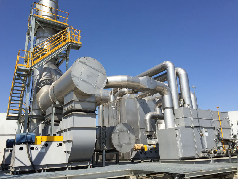
A vapor recovery compressor package moves recovered vapor between the collection header, the recovery process and the receiving system. The compressor is selected as part of the complete VRU, not on its own: suction conditions, discharge pressure, flow variation, vapor composition and safety requirements must match the rest of the package, and the package must match the tanks or terminal it serves.
Package scope at a glance
| Item | Project review |
|---|---|
| Compressor | Type, capacity, suction and discharge pressure, turndown, vapor compatibility. |
| Driver | Motor or driver, electrical supply, hazardous-area requirement, starting method. |
| Protection | Suction knockout, filtration, high-temperature protection, vibration monitoring, shutdown logic. |
| Flow control | Bypass, recycle or speed control for minimum and peak cases. |
| Connections | Inlet, discharge, drain, vent, instrument air, power, control interfaces. |
Compressor type selection
Four machine types cover most vapor recovery duty. The choice follows from the pressure ratio, the volumetric flow at suction conditions and how much liquid the vapor carries; composition and molecular weight then decide materials, seals and driver arrangement.
| Type | Where it fits | Ratio and flow | Wet gas and maintenance |
|---|---|---|---|
| Rotary vane | Small tank and terminal streams; modest rise; clean vapor. | Low to moderate rise, low to medium flow. | Poor tolerance of slugs; vanes and rotor surfaces wear. |
| Screw (dry or oil-flooded) | Continuous duty at medium to higher flows, including loading vapors. | Moderate rise per stage; two stages for larger ratios. | Takes more liquid when oil-flooded; oil and rotor clearance dominate maintenance. |
| Liquid ring | Wet, dirty or corrosive vapors with liquid in the gas. | Low rise per stage, lower efficiency. | Most tolerant of carryover; seal-liquid loop needs supply, cooling, disposal. |
| Reciprocating | Higher ratios, low suction pressures, a fixed discharge pressure. | Highest rise of the four; suits lower flows. | Least tolerant of liquid; valve plates, rings and packing are consumables. |
Where the ratio exceeds one stage’s limit, a two-stage arrangement is preferred, and low suction pressures push selection toward a machine designed for that duty.
What is inside a compressor skid
Skid packages are assembled, piped and wired as one unit before shipment, limiting site work to foundations, vapor tie-ins, utilities and commissioning.
- Main machine and driver – compressor, prime mover, drive and starting method, sized for the available supply and hazardous-area classification.
- Suction knockout and separation – drum or separator with demister, level instrumentation and automatic drain against slugs and heavy ends.
- Cooling – aftercooler and intercooling, keeping discharge temperature inside the limits of downstream seals and the receiving system.
- Lubrication – reservoir, oil pump, cooler, filters and pressure protection on oil-flooded machines.
- Control panel and instrumentation – pressure, temperature, level, speed and vibration signals wired into start/stop logic, alarms and shutdowns.
- Relief valves, interlocks and shutdowns – suction and discharge relief, high level, high temperature, high and low pressure and vibration trips, plus a defined restart sequence, coordinated in the control panel and instrumentation package.
- Baseplate, lifting and access – structural skid with lifting points, drip containment and access to exchange a major component.
Suction pressure band and tank back pressure
The compressor runs against a pressure band set by the tanks, header and receiving system. On tank vapor service an upper setpoint starts the machine and a lower setpoint stops it; the gap between them is the deadband that prevents short-cycling. Tanks, roofs and vents are designed for a limited pressure and vacuum range, so the band must sit inside it with margin before emergency venting. Too narrow a band causes frequent starts; too wide lets pressure swing further than the roof and seals allow. See oil storage tank vapor recovery.
Variable speed lets the machine follow the vapor the tanks actually produce, cutting recycle, energy use and low-load running time. Fixed speed with a bypass or recycle line back to suction or the header is simpler, but recycled vapor is compressed twice and raises suction temperature.
Common selection mistakes
- Sizing to the peak case alone – turndown, not peak capacity, decides behaviour in normal operation.
- Using the wrong molecular weight – light hydrocarbon and condensate vapor is heavier than the default figure used in preliminary work.
- Ignoring liquid carryover and water – wet vapor and slugs change type selection, knockout design and materials.
- Treating composition as constant – tank vapor shifts with temperature, product level and loading activity; the extremes set the design.
- Selecting the machine before the pressure band – suction and discharge pressures come from the tanks and receiving system, not from equipment on order.
- Forgetting the receiving system – discharge pressure, allowable temperature and any oxygen limit constrain the package as much as the collection side.
The VRU specification checklist lists the data that closes these gaps; VRU failure modes show what happens when they stay open.
Materials, seals and corrosive service
- Wet H2S (sour service) – hardness control and sulfide-stress-cracking-resistant alloys for wetted parts, with compatible seals and gaskets.
- Light hydrocarbons and aromatics – elastomer swelling and permeation drive single versus dual mechanical seals, or dry gas seals on larger machines.
- Water and condensate – low-point drainage, coating where condensate collects, attention to the wet-dry interface.
- Coastal environments – coating systems, stainless or coated fasteners, corrosion-resistant or lined components; crevices and skid-to-baseplate contact corrode first.
- Oxygen and solvents – elevated oxygen or solvent carryover can rule out certain seal liquids and change the recovery route.
Operation, maintenance and spare parts
- Oil condition – scheduled sampling; water and light-hydrocarbon ingress show up in the oil first.
- Wear items – valve plates, vanes, rings, packing and shaft seals set the maintenance interval.
- Drive train – belt tension or coupling alignment, bearing temperatures and driver checks, recorded for trending.
- Vibration and temperature – trending catches bearing degradation and liquid carryover before a trip does.
- Separator and drains – demister condition, drain traps, level control and condensate disposal on a routine.
- Safety devices – relief valves, switches, trips and shutdown logic tested on a schedule, restart sequence confirmed.
A practical spares holding covers oil and filters, seal and gasket kits, wear parts, bearings, switches and instrument spares – see VRU spare parts and service and installation and commissioning.
Frequently asked questions
How do I choose between a screw and a reciprocating compressor?
Start with the pressure ratio and the flow. Screw machines suit continuous duty at medium to higher flows and tolerate more liquid when oil-flooded. Reciprocating machines reach higher ratios and lower suction pressures but need good knockout, and use valve plates, rings and packing as consumables.
Can one package handle both tank breathing and loading vapors?
Often yes, but loading vapors arrive in bursts and differ in composition from breathing losses. The package is sized on the header balance with loading as the peak case, with capacity control efficient in the lower breathing case. One machine or two depends on how far apart the cases sit and the redundancy needed.
VFD or bypass recycle for capacity control?
Variable speed usually reduces recycled vapor, suction temperature rise and energy use, and handles wider turndown; bypass or recycle is simpler but recycles vapor. The deciding factors are turndown width, supply reliability and operating time at low rates.
What data do I need before requesting a package?
Minimum, normal and peak flow, suction and discharge pressure, inlet temperature, vapor composition, oxygen content, liquid carryover, operating schedule, available power, hazardous-area classification and receiving-system requirements. The VRU RFQ data sheet organises those fields.
Talk to an Engineer
Send the compressor duty and vapor data – flow range, pressures, composition, liquid carryover, site conditions and available power. We review the mechanical, compressor, separation and control interfaces together and respond with a package configuration and equipment list. For the wider system view, start from the oil and gas vapor recovery unit overview, or contact us directly.