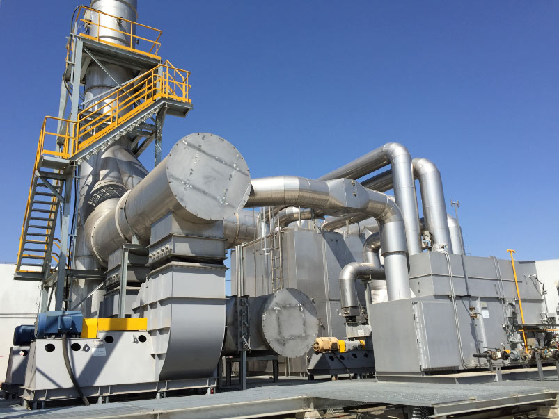

Storage tank vapor recovery controls hydrocarbon emissions from filling, emptying and temperature changes. A suitable system combines source collection, pressure management, liquid protection, recovery or treatment equipment and safe discharge control.
Where Tank Vapor Comes From
Tank vapor is the sum of mechanisms that differ in timing and composition; each must be estimated before equipment is selected.
- Working loss – vapor displaced as liquid fills the tank, plus loss of saturated vapor space during withdrawal. The largest and most predictable component at most terminals, driven by filling rate rather than ambient conditions. Product transfer and loading works the same way, so the two are reviewed together.
- Breathing loss – vapor expelled by daytime thermal expansion and drawn back as the tank cools at night. Temperature range, vapor pressure and vapor space volume set the amount moved.
- Standing and sliding losses – on floating roof tanks, exposed liquid at the rim seal, deck fittings and roof drains gives a continuous film loss, smaller than working loss but constant, which matters for compressor sizing.
- Flash and dissolved gas – light ends come out of solution when pressure drops or temperature rises at the tank inlet, and product arriving hot from a separator flashes appreciably.
- Leaks, open vents, sampling, gauging and maintenance – intermittent releases, easy to miss in a mass balance but relevant to safety.
How Tank Type Changes the Vapor Profile
The tank is the first emission control device: what sits above the liquid sets how much vapor exists.
| Tank type | Vapor character | Typical approach |
|---|---|---|
| External floating roof | Vapor space largely eliminated; losses concentrated at the rim seal and deck fittings | Usually not the primary target; dedicated arrangements where required |
| Internal floating roof | Deck seals cut evaporation, but the space under the fixed roof still breathes | Suction above the deck, with conservative pressure control to avoid deck damage |
| Fixed roof (cone or dome) | Largest vapor space; breathing, working and flash vapor all present | The usual candidate for a pressurized header to a recovery unit |
| Spherical or pressure storage | Little routine vapor; releases mainly on relief or upset | Routed to flare or relief, not a continuous recovery unit |
Floating roof tanks need their own treatment because the control device is mechanical and recovery equipment must not interfere with deck movement; see vapor recovery for floating roof tanks.
Pressure Balance in a Tank Farm
The recovery unit acts on a pressure, not on the tank directly. Every tank in a header has pressure and vacuum limits, and the collection system must stay inside that band at all times, including when the unit is down.
A workable design defines four points: the vacuum at which makeup or blanketing gas enters, the normal suction band, the pressure at which the relief valve begins to open, and the emergency relief setting. Between the normal band and relief there must be enough buffer volume, or response speed, to absorb a filling operation starting at low load. That deadband is set by tank size, filling rate and how many tanks change state together, and header pressure drop is evaluated at peak flow because back pressure at the far end is what moves tank pressure.
Products with incompatible hazard classes cannot be combined into one header without a documented review. Blanketing and vapor recovery are not alternatives: blanketing holds positive pressure and limits air ingress, while the unit removes hydrocarbon blanketing cannot consume. Where the header is sealed against air, oxygen monitoring and a defined shutdown response belong in the control scheme. See tank farm vapor recovery systems and refinery and tank terminal vapor control.
Recovery Route Options
| Route | How it works | Better suited when |
|---|---|---|
| Adsorption then absorption | Activated carbon equalizes concentration swings; hydrocarbons are stripped into a circulating liquid | Variable-concentration light hydrocarbon vapor, where a liquid destination exists |
| Compression with absorption or condensation | Vapor is compressed, then contacted with liquid or chilled to condense recoverable fractions | Richer streams or larger flows, including where vapor travels before treatment (compressor arrangements) |
| Condensation | Refrigeration cools the stream and condenses heavier hydrocarbons | Recoverable heavier components and a need for low residual vapor |
| Membrane | Selective permeation concentrates hydrocarbons in a recycle stream | Moderate flows where a compact skid and recycle loop are practical |
| Oxidation of residual vapor | Remaining vapor is destroyed in a thermal or catalytic unit | Low recovery value, dilute gas, or no safe recovery destination |
Most tank applications combine two of these: recovery ahead of an oxidizer lowers the duty it must carry, and the choice is settled by composition and by the site’s use for recovered liquid. Equipment families are summarized on our vapor recovery unit page.
Safety and Instrumentation Practice
Tank vapor is flammable and often enters the flammable range once it meets air, so the system is designed on the assumption that a flammable atmosphere can exist in it.
- Blanketing – nitrogen or fuel gas keeps tank pressure positive and limits oxygen ingress, with its own pressure control and low-pressure alarm, independent of the recovery unit’s control loop.
- Flame and detonation arresters – placed so that a flame path between tank and recovery equipment is interrupted. Selection depends on whether the flame is expected to deflagrate or detonate, which follows from piping length and layout.
- Area classification – electrical equipment, instruments and junction boxes are specified for the zone set by the site review; intrinsically safe circuits are common on headers.
- Lightning and static – bonding and grounding of tanks, piping and skids, provisions maintaining contact across moving floating roof components, and surge protection on field wiring.
- Relief and bypass – a defined emergency route so that loss of the unit cannot pressurize the header beyond tank design limits, plus low-point drainage and knockout ahead of the machine.
Breathing valves, isolation and emergency relief are reviewed against the tank pressure and vacuum ratings rather than specified in isolation.
Data Needed to Size a Tank Vapor Recovery Unit
A route cannot be selected from flow alone. This is the minimum we ask for, and it matches our VRU sizing and data checklist.
- Tank type, diameter, shell height, nominal volume and liquid level range
- Product slate and vapor pressure at expected storage temperature
- Normal and maximum filling rate, and emptying rate where product is drawn out
- Number of tanks that can fill, empty or breathe at the same time
- Vapor composition, or the lightest and heaviest components if no analysis exists
- Tank design pressure and vacuum limits, with relief valve settings
- Inlet product temperature range and expected flash vapor
- Oxygen content, and whether blanketing is installed or planned
- Liquid carryover potential, entrained water or solids
- Ambient conditions, elevation, utilities and recovered liquid destination
Missing items are usually what delays a proposal; flow quoted without tank pressure limits changes the equipment materially. Header piping, drainage and long-term degradation are covered under piping and maintenance considerations and vapor recovery unit failure modes.
Frequently Asked Questions
Should tank vapor be recovered or destroyed?
Recovery suits vapor rich enough to yield usable liquid where a safe destination exists. Destruction suits dilute or variable streams, or cases where recovering the hydrocarbon creates a handling problem with no offsetting value.
Can several tanks share one vapor recovery unit?
Yes, and that is the normal arrangement. The header is sized for tanks changing state together, and each tank keeps its own pressure and vacuum protection.
Does every storage tank need nitrogen blanketing?
No. Blanketing is chosen where the vapor space must stay outside the flammable range, where oxygen ingress would degrade the product, or where vapor partial pressure must be suppressed; where used, it and the recovery unit form one control system.
What causes a tank vapor recovery unit to trip?
Liquid carryover into the knockout or machine, high oxygen or hydrocarbon readings at the equipment boundary, low blanketing pressure, high discharge pressure or temperature, and instrument faults. A trip should return the header to a safe condition through the emergency route.
What vapor composition should we expect from crude or condensate tanks?
It varies with product and temperature. We see mixtures dominated by light paraffins, with heavier fractions during filling, and separator streams carry more dissolved gas. We size on the analysis, or on the dominant component range where none exists.
Talk to an Engineer
Send your tank and product data for a preliminary collection and vapor recovery route comparison.