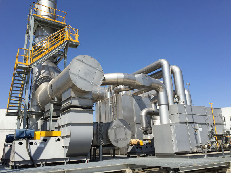

Vapor recovery system design starts with the vapor source, the gas composition and the operating conditions, not the equipment. A vapor recovery unit (VRU) captures hydrocarbon vapor from storage tanks, truck loading, marine terminals, refineries and process vents so the product is recovered instead of released or flared. Where a tank farm and a loading rack share one machine, the two sources behave in opposite ways.
Tank Farm Duty versus Truck and Rail Loading Duty
Tank vapor comes from working, breathing and flash losses – product movement, temperature swing, and light ends leaving solution at the tank inlet – so the flow is small and nearly continuous. Loading is a step function: nothing for hours, then vapor displaced at the liquid fill rate for one parcel. Rail loading adds more cars connected at once and a larger parcel per connection.
| Character | Tank farm | Truck and rail loading |
|---|---|---|
| Flow | Continuous and small | Batch, then a large step |
| Driven by | Breathing, working and flash losses | Liquid displacement plus evaporation |
| Design peak | Several tanks filling at highest ambient | All positions loading together at maximum rate |
| Dominant risk | Tank pulled below vacuum rating; valve lifted | Liquid carryover and slugging |
See railcar loading vapor recovery and truck loading vapor recovery.
Design Inputs That Fix the Loading Peak
The inputs below set the peak, and systems are usually undersized because it was taken from an average.
| Input | What it fixes |
|---|---|
| Simultaneous loading positions | Design peak and header size |
| Loading rate per position | Suction duty and return line size |
| Largest parcel and loading time | Buffer volume and response speed |
| Vapor return volume | Suction duty after evaporation |
| Vapor return temperature | Condensation in header and drains |
| Flow range, inlet pressure, temperature, pressure drop | Sizing across the whole duty |
| Composition, oxygen content, carryover risk | Technology, protection, materials |
| Operating hours and recovery target | What the design must demonstrate |
Vapor return volume and temperature
Vapor return volume is not the liquid volume loaded. It is the vapor displaced from the compartment plus vapor from the freshly loaded liquid, both of which grow with product and return temperature. A warm return carrying heavy ends drops liquid in a long, poorly drained header, and that liquid reaches the suction drum. Rack hardware is described under loading rack vapor recovery equipment.
Vapor Collection and Piping
The collection system decides whether the machine ever sees the peak it was sized for. A header that is generous on paper but sloped wrongly, or joined carelessly, delivers liquid and pressure excursions.
Branch merging and sub-headers
Take suction from the top of each branch, run branches into a sub-header before the common header, and size that header for the coincident case.
Slope, liquid collection and drainage
Slope vapor lines toward a collection point, with no flat runs or undrained pockets, and drain at every low point. Knockout drum and mist eliminator only work if liquid ahead of them can move.
Keeping the two headers from pushing each other
A loaded rack header rises while the tank header may sit elsewhere in its band. Joined without protection, a parcel starting as a tank fills can lift tank pressure-vacuum valves or pull tank pressure down. Use separate sub-headers, non-return or isolation on branches that must not be back-fed, and priority for the tighter pressure limit.
Flame and ignition protection
Loading vapor readily enters the flammable range where it meets air at an open connection. Flame and detonation arresters interrupt the flame path between tank and recovery equipment in both directions; the type follows piping length and layout. Instruments and junction boxes match the site’s classified zone, with bonding and grounding, and an emergency relief route so a trip cannot pressurize the header beyond tank limits.
Recovery Methods and When Oxidation Is Added
Four routes cover most tank farm and loading duties:
- Compression – raises vapor pressure so the stream can return to a process, fuel or sales-gas line; turndown and liquid protection matter.
- Condensation – refrigeration condenses heavier hydrocarbons where the vapor carries a recoverable product, with separator and liquid management behind it.
- Adsorption – carbon beds polish hydrocarbon vapor; design accounts for bed capacity, regeneration, temperature and contaminants.
- Combined schemes – condensation plus adsorption or compression plus absorption, where composition and target need two steps.
These families serve oil tank, gasoline, refinery and terminal, marine, truck loading and oilfield vapor recovery, so a package must be checked against actual process data – see the oil and gas vapor recovery unit page.
A final oxidation stage is normally necessary where the stream is dilute or variable, where recovery cannot reach the outlet target alone, where oxygen excursions rule out a consistent recovered liquid, or where vapor arrives at minimum recovery load. Recovery goes first so the oxidizer carries a smaller duty. Multi-duty sites are covered under refinery and tank terminal vapor control systems.
Pressure Band Control and Interlocks
The unit controls header pressure, not flow. Four points define the scheme: where makeup or blanketing gas enters, the band in which the package modulates suction, the setting at which a pressure-vacuum valve opens, and emergency relief.
The normal band sits inside the tank design limits with margin. The deadband must stop short-cycling without letting a starting parcel move the header into the valve’s range. Buffer volume absorbs the start of a parcel before the machine responds. Capacity spans near-zero at night through the peak by variable-speed drive, unloading or staging.
List interlocks explicitly and test each function separately: high knockout level, tripping independently of the alarm; high discharge pressure and temperature; low suction and low blanketing pressure; gas detection at the equipment boundary; loss of the recovered-liquid destination; and emergency shutdown with defined fail-safe valve positions. A PLC with HMI logs the parameters tied to the outlet target. Package detail is on the vapor recovery unit compressor page, the wider sequence under VRU engineering and system design.
Commissioning and Acceptance Testing
Preparation before the test
- Tightness test of header, branches and vapor return connections, with arrester elements installed.
- Calibration and loop checks on pressure, level, temperature and gas detection channels.
- Interlock, trip and emergency shutdown tests with set points verified against approved values, each proved separately and signed off.
- Drain and recovered-liquid routes proved by moving liquid to the destination.
- A loading programme agreed with operations: positions, rate, product, stable conditions.
- Test instrumentation and logging agreed in advance, including what counts as the official result.
What the test has to demonstrate
Header pressure stays inside the band through the design peak with the agreed positions loading together; the result at the agreed measurement point meets the site target; and a trip returns the header to a safe condition. Idle behaviour between parcels matters as much as the peak. See VRU installation and commissioning and vapor recovery testing.
Frequently Asked Questions
Can one vapor recovery unit serve a tank farm and a truck loading rack?
Yes, with separate sub-headers or isolation so the rack cannot back-pressure the tanks, priority for the tighter limit, and a machine sized on a parcel starting as tanks fill.
Why is the loading peak so much higher than tank breathing flow?
Different mechanisms. Breathing follows temperature and product movement over hours; loading displaces a parcel’s vapor in minutes at the liquid fill rate. Sizing on tank flow alone is why valves lift.
Is vapor return volume equal to the liquid volume loaded?
No. It is close to the displaced volume in a well-sealed system, but freshly loaded liquid also evaporates, so it grows with temperature.
Why does vapor return temperature matter?
It sets how much vapor must be moved and whether heavier components drop out in the header. A warm return through a long, poorly drained line reaches the suction drum as condensate.
When is an oxidizer needed behind the recovery unit?
Where the outlet target cannot be met by recovery alone, where much of the stream is dilute, or where recovered liquid has no safe destination on site.
Talk to an Engineer
Send the tank type and product, the loading positions that can run together with the rate per position, the largest parcel and its loading time, the vapor return temperature, and the destination for recovered liquid. We will return a preliminary configuration and proposed test. Reach an engineer through the contact page.